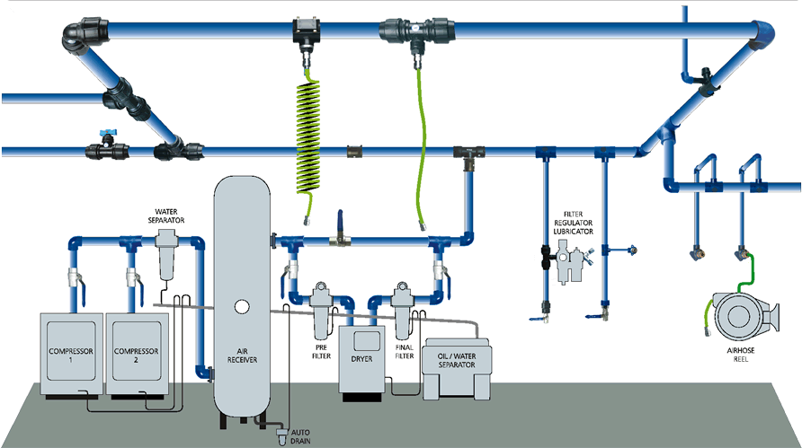
Compressed Air System Schematic
11 energy-efficiency improvement opportunities in compressed air Compressed air receivers Compressor schematic
Compressed Air Receivers
The fleet type submarine Compressor breathing compressors bauer Energy – compressedairducation
Diagram of compressed air systems. 1: compressor; 2: air receiver tank
Air/water separatorHow to choose an air compressor, according to science Compressor compressors receivers partsSchematic drawing of the compressor test system. schematic drawing of.
Compressor air chooseDfe: lesson 30. compressed air, water and steam Atlas copco air compressed compressor systems schematic pipe filtration controls maxairFilter system design.

Chapter 6 compressed air systems
Air compressed systems drawing submarine schematic hydraulic ballast manifold tanks main figure doc fleetsub maritimeWhat is the components of a compressed air system – zillions buyer Designing compressed air systemsCompressed air system energy dryer schematic drawing refrigerated piping systems industrial pipe filter storage familiar strategies aspects reduction implementing before.
Compressed air compressor diagram plant systems energy compressors efficiency engineering system opportunities improvement electricalPlumbing layout piping compressed airpro sufficient installations visit technix powdercoatguide Compressed air systems (energy engineering)Complete compressed air installations.

Air compressor shop lines diagram piping layout garage compressed line water workshop system pipe moisture plumbing filter separator set connection
Compressed air diagram schematic unit food compressor system water producing figure steam components dairy maintenance engineeringAir compressed receivers compressor system consumption secondary assembly systems capacity cooler after time over points before Compressor compressed systems pipeline leakage pointsCompressed air line.
Air compressed system systems installation guide compressor supply parts pressure low chapter installing typesCompressed air system schematic systems engineering energy fig .


How to Choose an Air Compressor, According to Science - Applications

Compressed Air Systems (Energy Engineering)

Designing Compressed Air Systems - FluidFlow | FluidFlow

Compressed Air Receivers

Energy – Compressedairducation

Diagram of compressed air systems. 1: compressor; 2: air receiver tank

Schematic drawing of the compressor test system. Schematic drawing of

air/water separator - Pirate4x4.Com : 4x4 and Off-Road Forum

Compressed Air Line
